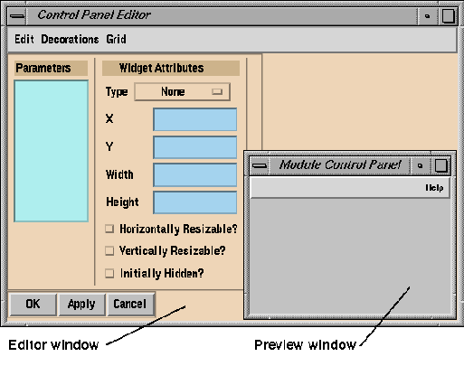
Figure 4-1 The Control Panel Editor
The Control Panel Editor enables you to create new control panels for modules, groups, and applications, and modify the appearance of existing control panels. You can define new menus on the menu bar and add or rearrange widgets on the control panel.
The Parameter Function Editor lets you establish relationships between parameters in adjacent modules in a map. The parameter value in the downstream module is then expressed as a function of the upstream parameter values.
This chapter describes how to use both these editors.
There are three places the Control Panel Editor can be used from:
The Control Panel Editor consists of an Editor window and a Preview control panel window. You stipulate the attributes of the panel in the Editor window, and the result is displayed in the Preview window.

When you edit a control panel, you can:
To save the menu and control panel configurations, click the
OK
or
Apply
buttons at the bottom of each window.
The widgets on the control panel allow you to control the value of the
module parameters directly.
An IRIS Explorer parameter may be one of three types of scalar quantity,
each of which can be represented as a widget or a menu item on the module,
group, or application control panel. A parameter can be:
For more information on parameters, see
Understanding IRIS Explorer Data Types
in Chapter 2.
The widget types are listed on the Type option menu (see
Figure
4-2) and described in detail in
Setting Module Parameters
in Chapter 2. All widgets must have a valid type selected, including those
you place on a menu. The widget attributes are listed in the rest of the
Widget Attributes pane.
The properties of the selected widget are shown in the widget properties
pane on the right. To display the widget properties, double-click on the
widget in the preview control panel.
To select a widget from the Control Panel Editor:
In
Figure
4-2, for example, the parameter
scale
is highlighted in the Parameters pane. The widget type selected for it on the
Type menu is a "Horz Slider" (horizontal slider). The widget is highlighted
in the preview window. Its properties are listed to the right under "Slider
Properties".
Figure
4-3
shows a selection of widgets, as well as the control panel
decorations.
Decorations are vertical and horizontal lines, frames and labels, available
from the Decorations menu (see
Figure
4-4). You can size them and move them around in the same way as you
manipulate widgets.
In general:
Widget similarities are shown in
Figure
4-1.
You can change the type of widget associated with any parameter by
clicking on the parameter name and selecting a new widget type.
The
Initially Hidden
button (see
Figure
4-2) lets you hide widgets under certain circumstances. These are:
Use the
Decorations
menu to select frames and dividers for your control panel. Once you have
selected a decoration, it is listed in the Parameters pane (see
Figure
4-4).
Four selection modes are available for the scrolled list widget (see
Figure
4-5). You can choose which mode suits the kind of parameter you have.
The options are:
Click on the widget to activate it in both the Preview window and the
Editor window. An active widget is enclosed by a
handlebox
of eight black squares (see
Figure
4-6).
The Widget Attributes pane in the Editor contains the absolute location of
the active widget. The origin of the control panel is in the upper left
corner. As you move the widget, the X and Y starting locations change. You
can type values directly into these text slots if you wish.
To resize a widget, you can:
For really precise adjustments, use the Grid menu to activate the grid.
You can size and position widgets exactly by snapping them to a grid.
The Grid menu contains a list of pixel resolutions that govern the
location and size of widgets. You can select any one of these options. The
default snaps to a grid size of 5 pixels.
When the
snap to grid
option is in effect, all subsequent widget moves and resizes occur only in
multiples of the grid size. If you resize a widget in this mode, it becomes a
factor of the grid's width or height, depending on the direction in which you
resize it.
The Properties pane contains information specific to the widget, including
the scalar type for dials and sliders and label information for option menus
and radio buttons. A plain button has the port name as its label.
The primitive type is important for the proper operation of the module and
should not be changed from its default value, which is what the underlying
module is expecting. However, you can change it under special
circumstances.
To change the widget primitive type, select an alternative from the
Properties pane of the Control Panel Editor.
To set the value of a widget, you must first select it. To select a widget
for editing, double-click on it in the Preview window with the left mouse or
click on it in the Parameters pane.
To select all the widgets in the control panel at once, use
Select All
on the Edit menu of the Control Panel Editor. To de-select them, click on the
background of the control panel.
You can change the value of dial and slider widgets by typing a new value
into the upper text slot or moving the widget pointer. You can also set
minimum and maximum values by typing them into the range text slots. You must
press
<Enter>
for settings to take effect.
You can also change the number of options in the Properties pane for radio
buttons and option menus. This might not have the desired effect, however, if
you add labels beyond those expected in the module itself.
A good example of this is the
Contour
module. It has three sets of radio buttons that control contouring in the I,
J, or K directions. Each radio button has two options: On or Off. If you add
a third option, such as Half On, to one of these radio buttons, the module
will not process it.
You can seriously confuse the Map Editor if you switch a module widget type
to one that is incompatible with what the module expects.
To dismiss the Control Panel Editor click the
OK
button.
The
Apply
button saves the layout information without closing the Editor window.
The
Cancel
button dismisses the Editor without implementing your changes.
You can link a parameter with a menu item on the module menu bar instead
of giving it a widget on the control panel. For example, instead of having
two file browser widgets on the control panel for opening and saving files,
you can set up a File menu with the menu items
Open
and
Close,
each linked to a file selector.
The Preview control panel has a default menu bar with an empty
Help
menu already in place (see
Figure
4-3).
For each parameter linked to the menu bar, you need to specify a widget
attribute in the Control Panel Editor as well. Use the
Initially Hidden
button to keep them from appearing on the module control panel.
To display the Menu Bar Editor, select
Menu Bar
from the Edit menu on the Control Panel Editor.
The Menu Bar Editor appears (see
Figure
4-7). You can create up to eight different menus, with up to sixteen
items on each menu, depending on the parameters you want to associate with a
menu item.
It will help the users of your modules if you follow the conventions for menu
placement; that is, File menu on the far left, then Edit menu, then your
other menus.
Set up your menus by typing the name of each menu in the text slots in the
Menu Bar Editor, for example,
File.
To save them, click on
Apply.
You can set up menu
stubs
for parameters that currently do not exist and add the items to the menu at a
later date if you wish.
To create the menu options for each item on the menu bar, click on the
Menu
push-button under the menu name. The Menu Editor is displayed (see
Figure
4-8).
You can create entries for the current menu. For example, reader modules
or groups that have reader functions will usually have
New
and
Open
entries in their File menus.
From the option menu next to the item name, you can set the action to be
taken when the user selects this item from the menu bar of the completed
module control panel.
The action items are:
If you choose
File selector, a button appears in the next pane, allowing you to
define the file selector parameter.
If you choose
Set param, the button appears again, with a text slot for
entering the name of the parameter.
If you choose
Script command, or
System command, a text slot appears for entering the name of the
command.
When you create a group or application control panel, you may wish to
promote a menu item from an individual module to the group control panel.
Unlike other widgets, which are promoted to the group panel along with their
associated parameters, the actual menu entry is not promoted. Only the
parameter passes to the group level. You must, therefore, create a new menu
for the group control panel and redefine the parameter as a menu item at the
group level.
When a number of connections fan into the same parameter input port, you
may wish to express the value on that port, as a function of some or all of
the fan in connections. For example you may wish to take the average value of
all the connections into the port.
The Parameter Function(P-Func) Editor (see
Figure
4-9) lets you set up relationships between the fan in values on an input
parameter port, so that the value of the parameter is expressed as a function
of one or more parameter values from the upstream modules.
To do this, you define each parameter in the P-Func Editor and then create
a mathematical expression that defines their relationship. Any change in the
value of the upstream parameter (or parameters) is then reflected in the
value of the input parameter.
You run the P-Func Editor from the module containing the parameter you
want to control. Before you can write a parameter function for an input
parameter, you must have one or more connections, from modules upstream,
wired to its port.
The title bar of the P-Func Editor (see
Figure
4-9) displays the name of the module for which you are creating the
parameter function. The window also has these components:
The P-Func Editor provides a simple set of expressions for creating
compound relationships among two or more input parameters in a module. You
can use all, or any subset of, the variables listed in the Variables box to
construct your function. For example, if you have two connections, with
variables A and B, you can type
A + 2*B, or
A/B, or
(A + B)/2
(the average of two inputs).
Table
4-2
lists the expressions accepted by IRIS Explorer.
The expressions are identical to the C language functions. For more
information, refer to the C language manual pages for each function.
IRIS Explorer accepts incoming parameters and turns them into floats by
default. If you want the parameter to have a different type, you can use one
of the typecast expressions (see
Table
4-2).
For example, if you have parameters A and B coming in as doubles and you
require them in integer form, you can cast them to type (long) as follows:
You can feed string parameter values to the P-Func Editor. Strings are
groups of alphanumeric characters The only operator you can use on strings is
+. The expression
indicates concatenation of the two terms. You can also create an
expression of the form:
in which case, IRIS Explorer returns the a string of the value of "12".
You can add like terms only. For example, the expression:
will produce an error.
If a string is not a number, it goes to zero. If it is a number, it
returns a value. For example,
returns a double.
You can create more complex expressions using several functions. Here are
two examples:
and
The upstream connections, supplying the values for the P-Func variables, need
not be related, i.e. they can come from unrelated modules or the same module,
it does not matter. If they come form different modules then there is no
relationship between
A
and
B; the parameter function relates
A
and
B
to the input parameter independently of each other.
In this example (see below), a relationship is created between parameters
from two different modules. The upstream module is
IsosurfaceLat. It has a
Threshold
parameter (shown as a dial), which will be wired to the minimum and maximum
level inputs of
Contour, the downstream module (see
Figure
4-11).
The parameter function is applied only when a upstream parameter (one
corresponding to a variable in the P-Func expression) is changed,
Threshold
in this example. It is not applied if you change the subject parameter,
Contour's
Min Level
or
Max Level
parameters, in this example. The change must be in the upstream parameter.
This example shows how to link parameters from different modules, and then
define the relationships between them. Launch the map named
simple, consisting of
ReadLat
connected to
IsosurfaceLat
connected to
Render.
To make a parameter connection (see
Figure
4-11):
To create a parameter function:
Click
Apply
at the bottom of the Editor window to implement your modification.
Click
Apply
again.
Close the P-Func Editor and save the modified map under a new name.
Now when you move the dial on
IsosurfaceLat,
Contour
fires as well. Set the number of levels in
Contour
to 2 or 3 and see what happens. The image should resemble that in
Figure
4-13.
The values of the contour lines, therefore, are always 30% to 80% higher
than the isosurface threshold.
If you click on the
Check
button, the P-func Editor tests the function you have entered to make sure
that it is valid and prints a message in the Message pane. The Editor window
stays open. For example, the second expression in the Parameter Function pane
in
Figure
4-14
has been entered incorrectly.
This is a summary of the steps you take to create a parameter function in
the P-Func Editor:
The P-Func Editor is case-insensitive.
Use the four buttons at the bottom of the Editor to save or reject
modifications to the input parameter. The buttons function as follows:
This example illustrates how to create a more complex parameter function
by establishing a relationship between three parameters. The parameters are
Contour's Min Level and Max Level and
IsosurfaceLat's Threshold.
First, create a map by launching a
GenLat
module, a
Contour
module, an
IsosurfaceLat
module, and a
Render
module and wiring them together as shown in
Figure
4-15.
To create an object in
Render
like the one in
Figure
4-15, open
GenLat's full-scale control panel and set these widgets as follows:
You want the threshold value of the isosurface to lie directly in the
midrange of the contour levels generated by the
Contour
module. To do this, you connect two output ports from
Contour
to an input port on
IsosurfaceLat, and set up a relationship between the two output
parameters and the input parameter.
To make these connections:
From now on, when you turn
Contour's Min and Max Level dials, the Map Editor sends these values
to IRIS Explorer's parameter interpreter. It evaluates the expression and
feeds the result to
IsosurfaceLat's
Threshold
parameter.
You can see the calculated value reflected in the position of
IsosurfaceLat's
Threshold
slider. There are now contour levels outside the isosurface.
You can change the transparency of the isosurface in
Render
so that you can see the contour values inside the surface as well. For more
information, see
Visualizing Data
in Chapter 3,
Using Modules.
Choosing Parameter Widgets
Parameter Types
Widget Types
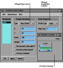
Figure 4-2 Selecting a Widget Type
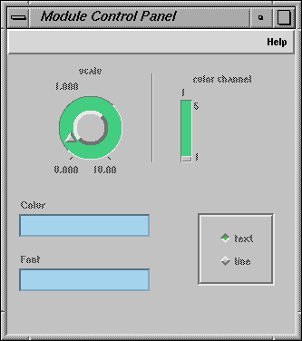
Figure 4-3 A Selection of Widgets
Widget
Similar to
Dials
Sliders, Text type-in slots
Radio buttons
Option menus
Text type-in slots
File browsers
Hiding Widgets
Widget Decorations
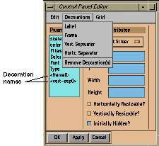
Figure 4-4 The Decorations Menu
Editing a Scrolled List
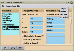
Figure 4-5 Scrolled List Properties
Moving and Resizing Widgets
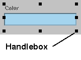
Figure 4-6 Widget Handlebox
Setting Widget Properties
Setting Widget Values and Limits
Creating Menu Items
Setting up the Menu Bar

Figure 4-7 The Menu Bar Editor
Setting up Menu Items
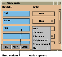
Figure 4-8 The Menu Editor
Menus in Group Control Panels
Using the Parameter Function Editor
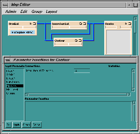
Figure 4-9 The Parameter Function Editor
Running the Parameter Function Editor
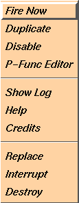
Figure 4-10 Module Pop-up Menu
Defining a Parameter Expression
Type
Expressions
Arithmetic
*, /, % (mod), +, -
Functions
min(A, B), max(A, B), exp(A), log(A), log10(A), pow(A, B), abs(A),
ceil(A), floor(A), rint(A), cos(A), sin(A), tan(A), acos(A), asin(A),
atan(A), atan2(A, B), cosh(A), sinh(A), tanh(A), length (returns the string
length in characters)
Typecast
(long), (double), (string)
Relational
==, !=, >, >=,
<,
<=
Boolean
&&
or AND, || or OR, ! or NOT
Ternary
A?B:C (if A then B else C)
Multiple
if then
clauses followed by a terminal
else
Typecasting Parameters
(long)A
(long)B
Using Strings
(string)A + (string)B
(string)(long)(3.3 + 8.9)
A + (string)B
(double) (7+3)
Combining Functions
min(sin(A * 3.14159/180.0)
cos(B*3.14159/180.0))
If sin(A) < 0 then this
If sin(A) > 0 then that
else the other
Linking Independent Parameters
Creating a Parameter Function
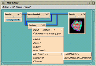
Figure 4-11 Connections for a Parameter Function
A * 1.3
A * 1.8
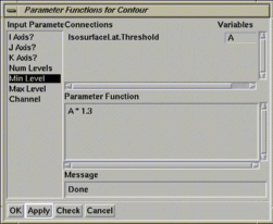
Figure 4-12 Parameter Functions for a Module
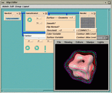
Figure 4-13 Simple Example with a Parameter Function
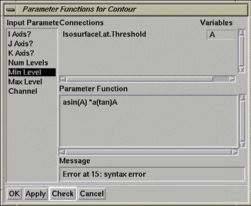
Figure 4-14 Messages in the P-Func Editor
Summarizing the Process
Saving the Parameter Functions
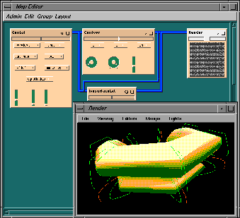
Figure 4-15 A Parameter Function Using Two Variables
Last modified: Mon Oct 13 16:13:41 1997
[ Documentation Home ]