Data is read into IRIS Explorer by the first modules in a map sequence, and the succeeding modules determine what form the results will take, and for what range of data values. For example, you can pinpoint areas where the bone is badly damaged by coloring the image according to bone density values.
The Module Librarian displays available maps and modules. You can launch
single modules from the Module Librarian, arrange them in the Map Editor, and
connect them to one another by their
data input
and
output ports.
These ports allow the flow of data between modules, the connections appearing
as wire-like blue lines. Maps are usually arranged so that the data stream
flows from left to right across the screen. You can also launch complete
maps.
The Map Editor and Module Librarian menus provide you with options for
manipulating the modules in a map. The modules themselves are accessible
through their
control panels.
These are rectangular panels, displayed on-screen, which contain
widgets, the means of adjusting module parameters.
The Map Editor (see
Figure
2-1) is the work area in which you assemble modules for the purpose of
organizing them into an operational map. A map is analogous to an
application, in that it comprises a series of algorithms performing
mathematical operations on data. Each module represents one discrete
operation on the data.
To bring up the Map Editor, type
explorer
at the shell prompt in the shell window.
The Module Librarian, log window and Map Editor appear.
To exit from the Map Editor, open the Admin menu and select
Quit. When you do this you will be prompted to confirm
prior to quitting IRIS Explorer.
You can select, copy, duplicate, delete, move, single or multiple modules
by using the Map Editor. The modules may be free-standing or already wired
into a map.
Use the Map Editor pull-down menus to:
Some of the Edit menu options have keyboard shortcuts listed next to them.
Once a map is set up in the Map Editor, you can run it so that the modules
fire and send data to one another. You can also incorporate several modules
into a group or an application (see
Chapter
5,
Creating Groups and Applications).
The object visualized in
Figure
2-1
is a curved torus, generated by
GenLat.
The Module Librarian (see
Figure
2-2) is a file browser and selector that provides access to IRIS Explorer
modules and maps through its scrolling columns and Librarian shelf. Each
Module Librarian has the name of its host system on the title bar.
Use the Module Librarian and its menus to:
The act of bringing a module or map from the Module Librarian into the Map
Editor and activating it is called
launching. To launch a module or
map, you can:
Maps in the Module Librarian are colored blue, modules are beige.
Use the scroll bars in the Module Librarian columns to scroll up or down
through the lists of available modules and maps. To scroll easily through the
module categories:
If you use the file browser to launch a module from a directory, the
module comes up in the current launch position, which is the active point in
the Map Editor. You can change the launch position by clicking the left mouse
button on another spot in the Map Editor background before you launch the
module. The next module is launched at that site.
To launch a module or a map from a remote system, select the remote host
Librarian from the Hosts menu by clicking on the host name and then selecting
the maps or module you want. You must first install the host in your host
list, using the
New Host
option on the Hosts menu.
You can launch as many copies of a module as you like, although some
modules might require special window server resources
(footnote)
. If you have more than one copy of a module in a map, the second copy will
have the number
<2>
after its name. The third will have
<3>, and so on.
Maps, in the Module Librarian, can be identified as blue. You can launch
a new map in the Map Editor by the
drag and drop
method from the Module Librarian (see
Launching a Module
).
If the map you want is not listed in the Module Librarian, you can select
Open
from the Module Librarian File menu. Use the file browser to find the
directory and then choose the map.
The top left module in a map is always launched at the launch point.
If you want to start IRIS Explorer and launch a particular map at the same
time, you can use the UNIX command line option
-map
with a filename.
Type:
The Map Editor opens and the map is launched and displayed automatically.
If you are not in the directory where the map resides, either change to that
directory before typing the command, or use the full pathname of the map, for
example,
/usr/explorer/maps/cfd.map.
Use the Module Librarian File menu to save your maps. You must save all
IRIS Explorer maps with the filename extension
.map; otherwise, IRIS Explorer will not be able to find the file when
you try to open it again.
Click on the module title bar to select a module. The title bar and access
pads will be highlighted in white. (See
Selecting a Module).
A file browser comes up, and you are required to enter a filename for the
map, for example,
NewMap.map.
From the File menu you can select:
Modules can be saved only as part of a map, but you can save incomplete
maps and bring them up later for further work.
You can remove some or all modules from the Map Editor at a time.
To remove the current map completely, select
Destroy All
from the Map Editor Edit Menu.
To destroy only some of the modules in the map, highlight the modules (see
Selecting a Module) and select
Destroy
from the Map Editor Edit menu.
To remove a single module, select
Destroy
from the module pop-up menu (see
Using the Pop-up Menu).
To bring up a new version of the module, launch the module again from the
Module Librarian. The new version of the module will be numbered
<2>
(or
<3>, if it is the third version to be launched).
This example illustrates how to launch an existing map from the Module
Librarian and carry out some simple operations.
Figure
2-4
shows the map you should see on your screen. It visualizes the data in the
file
/usr/explorer/data/lattice/testVol.lat.
On workstations without two-sided lighting the isosurface in
Render
may be dark. Change the Flip Normal? option on the
IsosurfaceLat
control panel from
No
to
Yes
to display the geometry properly.
The
simple
map is a three-module map, consisting of:
All the module control panels are displayed with their wiring connections
to one another visible. There is also a full-scale control panel for
Render's volume visualization. For more information on control
panels, see
Resizing the Control Panel.
When you first launch a map, all the module title bars and access pads are
highlighted in white, to show they are selected. You can move the entire map
by dragging on one title bar.
Before you can move individual modules, you must deselect them. Do this by
clicking on the background of the Map Editor. A module is reselected if you
click on the title bar.
You can:
The internal portion of the module consists of:
See the
IRIS Explorer Module Writer's Guide
for more information on the module core.
The visible portion, or control panel, which appears in the Map Editor, is
a rectangular window that contains:
The control panel has three forms, which are described in
How Modules Work. You can direct the activity in
the module core through the ports and widgets on the module control panel.
Modules accept data on their input ports, and pass it along via their
output ports after they have modified it. When a module acts on data, or
executes, it is said to
fire. A module may
be turned off, or disabled; and it can be fired on a computer other than the
one where you are running the Map Editor.
IRIS Explorer modules can be grouped according to their general function
(see
Table
3-1
in Chapter 3 ). They can:
Of these, the
Render
module stands on its own. It is the means whereby the data passing through
the map is visualized and is likely to be an integral component of most maps.
Once the data has been visualized as an object in the
Render
window, you can use the graphic capabilities of
Render
itself to enhance certain aspects of the object and to view it from various
angles.
The other modules operate on the data in various ways to produce a
geometric object that makes it easier to understand, interpret, and
extrapolate from the original data.
Render
and some of the more commonly used modules are described fully in Chapter 3.
To decide which modules you want in a map, you need to have more
information about what each one does, what data it accepts, and what it
produces for other modules to use, as well as what parameters it can have.
You can find information in these places:
When you launch a module from the Module Librarian, the module control
panel (see
Figure
2-6
through
Figure
2-8) appears in the Map Editor. Module control panels are rectangular
windows that give you access to the capabilities of the module core via two
main channels:
The control panel also has:
Before you can move or save a module, or use any of the Edit Menu
operations on it, you must select it.
To select a single module, click on the module title bar with the left
mouse button. The title bar and both access pads are highlighted. You can
move the module around the Map Editor by holding down the left mouse button
and dragging the mouse.
To select more than one module at a time, you can
lasso
them by clicking in the background of the work area, holding down the left
mouse button, and sweeping out a rectangle that encloses the desired modules.
When you release the mouse button, all modules that are completely enclosed
by the lasso will be selected. Alternately, you can hold down the
<Shift>
key and click on each module in turn.
To select all the modules currently in the Map Editor, open the Edit menu
and click on
Select All.
Use the
<Shift>
key with the
sweep
gesture to add more modules to an already selected group.
To deselect all selected modules, move the cursor off the title bar and
click any mouse button. To deselect one module, hold down the
<Shift>
key and click on the module.
The sizing buttons let you switch between the different forms of the
module control panel. When you first launch a module, it appears in the
Diminutif form (see
Figure
2-7), which shows the title bar, port access pads, and general widget
layout.
The full-scale panel shows details of the widgets and the parameter
values. You can move it outside the Map Editor window and enlarge it as much
as you wish. You can also use the
Maximize
and
Minimize
buttons to open the maxi control panel to full-screen size or to iconify it.
The maxi control panel shows the names, ranges, and current values for
widgets. It also has a menu bar with a Help menu, but does not show the
ports.
To close a maxi control panel, click on the left button of the title bar
and select
Close
from the Window menu, or double-click quickly on the left button of the title
bar. The full-scale panel disappears but the Diminutif control panel remains
in the network.
If you are working with a group of modules, use the
Select All
option from the Map Editor Edit menu and then choose
Make Micro
or
Make Mini
from the Layout menu to swap between these forms. You have to open each
full-scale panel individually.
If the maxi control panel disappears under other windows on the screen, you
can pop it up again by clicking on the
Maximize
button on the Diminutif or micro control panel.
The module pop-up menu (see
Figure
2-9) appears when you click on the title of the module control panel with
the right mouse button. You can choose any one of these options:
The Drop Icons at the bottom of the Map Editor window can also be used to
perform operations on a single module or many selected modules by dragging a
module onto the icon. Press the middle mouse button over the module control
title bar. This will show the "drag cursor", a representation of a module.
Keeping the middle mouse button pressed, drag the cursor to the required icon
and release to perform the operation.
If the module dragged has been previously "marked for selection" then the
operation is applied to
all
the selected modules, otherwise the operation is only applied to the dragged
module.
Destroy,
Replace,
Help,
Show Log
and
Disable/Enable
icons provide the same functionality as above options in the module pop-up
menu, but can be applied to many modules.
Disconnect
and
Reconnect
icons provide an alternative to using the options on the edit menu.
To open this window, click on the title bar of the control panel
with the right mouse button and select Help from the pop-up
menu (see Figure 2-9).
To close the Help window, click on the left button of the title bar
and select Close from the Window menu, or double-click quickly
on the left button.
The modules are listed alphabetically and described in detail in
the IRIS Explorer
Reference Pages and in their individual Help files and
man pages.
This example illustrates the first steps in creating a map.
You now have the basic components of a map in the Map Editor.
A map name must have
.map
as a suffix for IRIS Explorer to recognize and treat it as a map, for
example,
incomplete.map.
When you have typed in a name, click on the OK button.
You can add the map to the list in the Module Librarian by editing your
personal configuration file. This procedure is described in
Appendix
A,
Configuring Your IRIS Explorer Environment.
To launch this map and connect the modules, go to
Wiring Modules Together.
Modules communicate by passing data from one to the next through their
input and output ports (see
Figure
2-10
and
Figure
2-11). Once you have modules in the Map Editor, you can connect them
together individually or severally, disconnect them, change your mind about
connecting them, and alter the appearance of the connecting wires.
Each module control panel has two port access pads, one for input ports
and parameters on the left of the control panel, and one for output ports and
parameters on the right. A single module can have several input and/or output
ports.
Data port names are listed first on the port menu, parameter port names
are listed next, followed by synchronisation port(s). The port name is
followed by the IRIS Explorer data type that it can accept; that is,
Lattice,
Pyramid,
Geometry,
Parameter,
and
Pick.
Parameter ports are associated with widgets. If the port is optional, the
type is followed by
(Opt).
A connection is required on a module port unless the port is marked as
optional (Opt). For example,
GenerateColormap
has an optional input port. A module will not operate properly in a map
unless all its required ports are connected to compatible ports on other
modules and are receiving data.
A module with parameter-based widgets always has an input and an output
port for each parameter. For example,
BlendImg
has two data input ports and one parameter input port for
Blend
(see
Figure
2-10). It has one data output port and a corresponding parameter output
port for
Blend
(see
Figure
2-11). Parameters are passed through the output ports and you can set and
connect them so as to control widgets on other modules.
The synchronisation ports
Fire
and
Firing Done
are present on all modules, and as their names suggest can be used to control
a firing sequence. See
Using the Synchronization Ports. A
Firing Done
output port can be connected to a
Fire
input port. Loop controller modules have an additional output port
Loop Ended. See
Constructing Loops.
To select an input or output port, click on the associated access pad
using the right mouse button. A list of the input or output ports and
parameters associated with that module appears (see
Figure
2-10
and
Figure
2-11).
IRIS Explorer makes use of five data types: Lattice, Pyramid, Geometry,
Parameter, and Pick. They are explained in
Understanding IRIS Explorer Data
Types. You can connect only input and output ports that accept the
same data type.
For example, you can connect an output port called
Colormap - - Lattice
to the input port called
Input - - Lattice
but not to one called
Input - - Pyr.
Only an output port of type
Pyramid
is compatible with the latter.
When you click on an output port to select it, all the compatible input
ports on other modules in the Map Editor are highlighted in green. Likewise,
when you select an input port, all compatible output access pads light up in
a different shade of green. Incompatible ports are grayed out, so they cannot
be selected.
Since a lattice can assume many forms, the Map Editor does type-checking
for types of lattices and lets you connect only those modules that accept and
produce the same type of lattice. For more information on lattices, see
Chapter 4 in the
IRIS Explorer Module Writer's Guide.
Wiring modules together is a simple process. You can wire input to output
port or output to input port.
Figure
2-12
shows a connection from the output port of
Contour
to an input port of
Render.
To make the connections, follow these steps:
To cancel an incomplete connection, when only one port has been selected,
click on the background of the Map Editor.
You exit the wiring mode automatically once a connection has been made.
You can wire more than one input port to a given output port, and vice
versa, provided that the data types on the ports are compatible. This is
called
fanning
connections out and in.
Figure
2-13
shows a
ReadLat
module with two connections on its output port, one to the input port of
Contour
and one to the input port of
Isosurface. To make these connections:
To connect an input port to the output ports on several different modules,
follow the same procedure.
You may wish to disconnect a module or a number of modules completely from
the map, or you may wish to simply break a single connection, between two
modules. To break a single connection between two modules, follow these
steps:
The connection between the modules is broken and the blue wire disappears.
This method is useful if you wish to break only one connection.
If you wish to break all a module's connections then it is easier to
"disconnect" the module, rather than breaking each connection in turn.
There are two ways to disconnect a module:
When you use
Disconnect, IRIS Explorer will "remember" a module's connections so
that they can be re-wired later if desired using
Reconnect. If another disconnect operation is applied to it, only the
connections most recently broken will be "remembered".
The
Reconnect
operation, using either the Map Editor
Edit
menu, or the
Reconnect
drop icon can be applied to a module after a
Disconnect. This operation will attempt to restore its connections to
the state prior to the last
Disconnect. If an individual connection to another module cannot be
re-instated, for example the other module has been destroyed, then that
connection will be skipped. If a connection has already been re-instated, for
example the user has already manually wired it up, then again the connection
will be skipped. The operation will also work on a module that has been
destroyed and re-launched.
You can change the direction, or slant, of the wires that connect the
modules in a map using
Wires
on the Map Editor Layout menu. Each option to
Wires
changes the alignment of the wires between modules, as their titles
indicate.
To change the slant of the connecting wires, choose one of the three
options,
Pt to Pt,
Right Angle,
or
Diagonal.
Click on each one in turn to see its effect.
It is an art to keep the wires in a map distinct and disentangled.
However, no damage results from their being crossed or threaded underneath a
module. The map merely becomes a little harder to read.
You can create more aesthetic maps by collapsing several modules into a
group module. In this case all the selected modules disappear and are
replaced by one control panel of your own design. For more details, refer to
Chapter
5,
Creating Groups and Applications.
This example illustrates how to connect modules to make a functioning map
(see
Figure
2-14). In the previous example, you saved a set of four modules.
Launch the map by dragging and dropping it in the Map Editor. Then wire
the modules together and set widgets as follows:
Notice that
Contour
has two connections on its input pad, but they go to two separate input
ports.
If you want to keep the finished map, remember to save it again.
When a module is activated, it fires and the user function operates on the
data it has received from its input ports. As the module fires, its title bar
turns yellow, and stays yellow until the module has completed execution. The
color change is called
execution
highlighting. (This highlighting can be turned off by toggling the
Exec Hilite
option on the Layout menu). This might take a fraction of a second or several
minutes, depending on the complexity of the user function and the amount of
data it is processing.
Firing can occur at several different stages of the map-building process.
A module fires when:
You can force a module to fire by:
This is useful for modules that have no parameters, for example, many of
the image-processing modules, or if you do not want to change a parameter
value.
Each time you alter a parameter or change a connection in a map, in effect
feeding in more or altered data values, the affected modules automatically
fire again. This can cause a cascade of firings downstream of the module.
For an in-depth explanation of the mechanism behind module firing, see
Appendix B of the
IRIS Explorer Module Writer's Guide.
When a module fires successfully a connection from its
Firing Done
port to a downstream module's
Fire
port can cause the downstream module to fire in exactly the same way that
sending new data to the module would cause it to fire.
You can therefore use these synchronization ports to
There are a number of ways in which module(s) can be disabled:
Disabling a module is useful if:
When modules fire in the Map Editor, they often generate informative text
messages. For example,
PrintLat,
PrintPyr, and
PrintPick
all output text strings describing their data. Other modules may also
produce messages in the course of a map cycle, all of which are logged by
IRIS Explorer. You may be interested in seeing all generated messages, or
only those put out by a particular module.
The Map Editor Log window captures all the messages generated by modules
in the Map Editor. It is a read-only scrolling text window that typically
appears below the Map Editor (see
Figure
2-16). Messages in the window scroll upward, with new lines inserted
until the size limit of the Log is reached. After that, lines are deleted.
The Log lists the output from each module as it occurs, with the name of the
generating module as a prefix to each line.
You can hide or display the Map Editor Log by toggling the
Log Window
option on the Map Editor Layout menu.
To see text messages for an individual module without having to reviewing
the entire Map Editor Log, you can open and examine a Module Log (see
Figure
2-17). Each Module Log displays messages generated by that module alone.
Open the Module Log by selecting
Show Log
from the module pop-up menu (see
Figure
2-9).
You can cut and paste the information displayed in the Log windows into
other windows. By selecting the
Editable Log
option from the Log window pop-up menu (see
Figure
2-18) you can type further text into the window, if, for example, you
wish to annotate the output. The menu appears when you click the right mouse
button in the Log window. To change the Log back to a read-only window (the
default), select the
Un-Editable Log
option. The other two options let you clear the window and save its
contents.
You can also send the log output to the UNIX shell from which you launched
IRIS Explorer. To have text messages sent to
standard output, start IRIS Explorer with this command:
If you use this option, you can still use the Log windows for reviewing
text messages.
In IRIS Explorer, the data that modules accept and pass on is
characterized by the
data type. The data type is the form that data
takes in IRIS Explorer. There are five IRIS Explorer data types: lattice,
pyramid, geometry, parameter, and pick.
All data is passed through the module input and output ports, each of
which accepts or outputs only one data type. Modules may, however, have
several ports with a different data type on each one.
The IRIS Explorer data types are:
This is the most commonly used data type.
Parameters are used to set values for slicing planes, error tolerances,
quantities, and filenames.
It is possible to define new data types in IRIS Explorer, and you may find
that the input and output port menus of some modules list data types in
addition to those described here. Those are user-defined data types. They
work exactly as IRIS Explorer data types do, handling data in a specific
format.
All the data types are described fully in
the
IRIS Explorer Module Writer's Guide.
The IRIS Explorer data types represent groups of data. A given instance of
a data type on a port can be generic or highly specific. For example, a
module may have an input port of Lattice type defined so that it will accept
a wide variety of lattices of different sizes, or so that it will accept only
2D scalar lattices of real numbers with uniform coordinate mapping.
For example, the
Contour
module accepts a Lattice data type on its input port, but the lattice must
have two or three dimensions. If you try to pass it data in the form of a 1D
lattice, you get an error message.
The module definitions give the data type specifications for the ports on
existing modules. When you build a module, you can define each port as you
like. The more general the specification for a port, the more modules you can
connect to it (but the harder the module is to write).
If you have any doubts about port compatibility when you connect modules
into a map, you can check the data types acceptable to each module by:
Certain modules can accept a pyramid or lattice data type and output a
lattice or geometry data type after performing a data conversion. These
include
PyrToLat,
LatToGeom, and
Contour. Modules with several input ports may be able to accept two or
more different data types, one on each port. For example,
Streakline
has input ports for a lattice and a pick and an output port for geometry.
Render
has input ports for geometry and parameter data and output ports for lattice,
geometry, and pick data.
Table
2-1
lists some of the IRIS Explorer modules according to the data type (Lattice,
Pyramid, Geometry or Pick) they can accept on an input port.
Some modules that accept lattices are further defined by whether they can
accept 1D, 2D, or 3D lattices, or a combination. For details, refer to the
input port specifications of each module in the
IRIS Explorer Reference Pages.
Table 2-2 lists some IRIS Explorer modules
according to the data type (Lattice, Pyramid, Geometry or Pick) they
can produce on an output port.
All modules that have input ports for parameters also have output ports for
them.
Module parameters allow you to set and change scalar values for each
module. For example, a parameter called
Min Range
that accepts integers may let you set the minimum value for a range of
temperature values for the module.
Parameters are controlled through
widgets
on the module control panel. Widgets are mechanisms for regulating a module's
parameter values. The parameter names are given on the module's input port
menu and on the full-scale control panel. A single control panel may contain
a number of widgets, each controlling a different parameter.
Widgets include buttons, sliders, dials, text slots, scrolled lists, radio
buttons, option menus, and file browsers, as well as drawing areas.
Buttons are rectangular or diamond-shaped widgets that let you select a
value or switch a specific parameter on or off. They come in two styles (see
Figure
2-19):
Use the left mouse button to click the buttons on and off.
Sliders (see
Figure
2-20) are either horizontal or vertical bars that let you increase or
decrease the value of a parameter in discrete steps. Sliders generally have
integer values.
Each slider has:
To change a parameter value, place the mouse cursor on the
thumb
and hold the left mouse button down while you push or pull the slider along
its bar. The current value changes as the thumb moves. When you release the
mouse button, the new value is sent to the module.
To move the bar to the cursor position, place the cursor in the slider
slot and click on the middle mouse button.
Dials are circular widgets that allow the continuous adjustment of a
parameter value between set limits (see
Figure
2-21). Like sliders, each dial has a title and slots showing minimum,
maximum, and current values. You can type new values into any slot (remember
to press
<Enter>), and you can also change the current value by turning
the dial pointer. Dials generally have float values.
The dials have a vernier action, in that you can use the pointer for
coarse settings. Place the cursor on the pointer and push it clockwise or
counterclockwise while holding the left mouse button down. The values change
linearly from minimum to maximum through a single revolution of the pointer.
To make a fine adjustment to the parameter value, place the cursor on the
dial center and push it clockwise or counterclockwise. The values increment
or decrement in minute steps, and the inner dial revolves 50 times for one
revolution of the pointer. This is useful for fine-tuning adjustments to a
parameter that spans a large range of values, or one that increments its
value in minute steps.
Text type-in slots (see
Figure
2-22) accept alphanumeric characters.
Text type-in slots appear in some input modules as part of a file browser
widget (see below).
The file browser widget appears in modules that read or write files from
or to the file system. To use the file browser, you must have the full-scale
control panel of the module open (see
Figure
2-23).
The file browser has two windows:
You can list the files in any subdirectory on your system. Rather than
having to type a filename into a text slot on the module, you can simply
select the file from the file browser. You can move up a directory hierarchy
by selecting the
../
entry (the first one in the list).
To select a file or directory from the Contents list, double-click on the
name.
If your selection is a directory, the file browser displays its contents
in the Contents window and its path and name in the Selection window. If it
is a file, it sends the filename to the module. The filename appears in the
Diminutif control panel text slot and the module fires.
To open a file, you can also click once on the filename to select it, and
then click on the
OK
button. The filename appears in the text type-in slot of the Diminutif
control panel, and the module fires.
You can use the file browser to traverse directories in a completely
different directory tree, in two ways:
Click on the Current Directory option menu, choose the item you want from
each menu, and click on it to get to the next menu level.
Option menus and scrolled lists let you select one or more items from a
group of options.
Option menu buttons present a menu from which you can choose one option at
a time. The option may be a value, a range of values, or a property, such as
uniform or curvilinear (see
Figure
2-24). The option menu buttons are rectangular, with a small raised bar
on the right.
A scrolled list widget (see Figure 2-25) lets you select one or more items from a list of
options that may extend beyond the current list window. You may be able to
choose one option or several options at a time, depending on how the
properties of the particular list were defined when the module was created.
Click on an item to select it. If the scrolled list allows you to select
more than one item, click on all the items you want to select.
A drawing area is a blank rectangle on the control panel in which an image
or visual object can be displayed (see
Figure
2-26). For example, the modules
DisplayImg
and
Render
have drawing areas on their control panels.
The window may take up varying amounts of space on the control panel. When
you enlarge the control panel, the drawing area may be enlarged
proportionally. Click on the
Maximize
button of the full-scale control panel to open up the control panel to
full-screen size.
This example illustrates how you can affect an object in
Render
by using widgets to change parameter values. Launch the map named
widgets
(see
Figure
2-27) by dragging and dropping it in the Map Editor. It contains five
modules:
On workstations without two-sided lighting the isosurface in
Render
may be dark. Change the Flip Normal? option on the
IsosurfaceLat
control panel from
No
to
Yes
to display the geometry properly.
Modules and maps are organized into categories in the Module Librarian.
Figure
2-28
shows one category, called
Modules.
You can reorganize the contents of these categories, displayed in scrollable
columns, as described below.
You can organize modules differently for each system on which you run IRIS
Explorer. For example, you may create a category for each remote host, or for
all the complete maps on your system.
To create new categories in the Module Librarian, select
To hide categories in the Librarian, click on the category title with the
right mouse button and select
Hide
when it appears.
To redisplay the category, select the category name from the Categories
menu.
To update a category, select
Update
from the Display menu after you have added new modules or maps.
You cannot delete categories, only hide them.
When you choose
Update
from the Display menu, new categories that have not been saved already are
deleted. To save new Librarian categories, see
Saving the Librarian
Configuration.
You can move maps or modules from an existing category to a new one by
dragging and dropping them in place. Items in a category can be ordered by
user preference, which is not necessarily alphabetical. You may want to put
frequently launched modules at the top of the list and leave the others lower
down.
Plan the order of your modules before you move them. New modules are added
at the end of the list, and once they are in place, they cannot be moved
again within the category.
The Librarian shelf (see
Figure
2-2) is a storage area for modules. It is like a bookshelf where you
place books to which you often refer. For example, you might stack modules
that you use a lot, such as
Render,
DisplayImg, or modules of your own creation, on the shelf. Shelved
modules are still available from the Module Librarian as well.
To place a module on the shelf, use the
drag and drop
technique. Once a module is on the shelf, you can launch it immediately or
leave it there to be launched later. You can launch it repeatedly from the
shelf.
Use the
Delete
option from the Module Launch menu (see
Figure
2-3) to remove a module or map from a category or from the Librarian
shelf.
You can restore a module you accidentally removed by selecting
Update
from the Display menu. It restores the original setting, so you also lose any
unsaved changes you have made to the Librarian.
Once you have arranged the IRIS Explorer modules and maps in categories
and on the Librarian shelf to your satisfaction, you can save the new
organization for future operations.
However, the
.explorerrc
file contains more information than IRIS Explorer provides when you save a
new configuration, so you should edit the file rather than overwrite it. Add
lines of the form
To set the module path, that specifies the directories to search for
modules, and for further configuration commands see
The .explorerrc Configuration File
in Appendix A.
When all the launched modules have been connected and your map is
operational, the modules fire and an object becomes visible in the
Render
or
DisplayImg
window -in theory, perhaps. In practice, this does not always happen. Here
are a few common problems and ways to fix them.
If a module port is
required,
then it must be receiving valid data from an upstream module in order to work
properly. All ports are required unless marked as
Opt(ional).
A message to this effect may appear when IRIS Explorer starts up. It means
that you do not have enough disk space to run IRIS Explorer properly. You
can:
If nothing appears in your Render window, try the following procedure:
This brings an object that may be out of the viewing area into the center
of the window.
If you have changed object parameters, but the changes do not appear in
the object, try the following procedure:
If the lattice is 1D or 2D, such as an image:
If the lattice is 3D, such as a volumetric dataset:
See
Slicing Volumetric Data
in Chapter 3 for more information about using slicers.
If you want a map to be displayed in the Module Librarian after you use
Update,
the map must be in a directory that the module Librarian recognizes.
To ensure this:
The default directory is
/usr/explorer/maps/*.
This output interferes with the communication between the Local
Controller, which is needed by the remote Module Librarian, and the
Global Controller, which starts up the Local Controller on the remote
system.
The offending command and its output must be removed before you can
run the Module Librarian on that remote system.
The best place for such output is the .login file. Other
programs besides IRIS Explorer get confused and do not work properly
when there is output from the .cshrc file.
The Map Editor
Opening the Map Editor
Quitting the Map Editor
Editing Maps and Modules
Alternatively you can use the drop icons at the bottom of the Map Editor
window for some module operations such as destroying, disabling/enabling and
disconnecting/reconnecting, see
Figure
2-1.
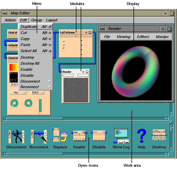
Figure 2-1 The Map Editor
The Module Librarian
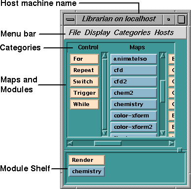
Figure 2-2 The Module Librarian
Launching a Module
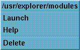
Figure 2-3 Module Launch Menu
Finding a Module in the Librarian
Placing the Module In the Map Editor
Launching a Map
explorer -map filename.map
Saving Maps and Modules
Removing Maps and Modules
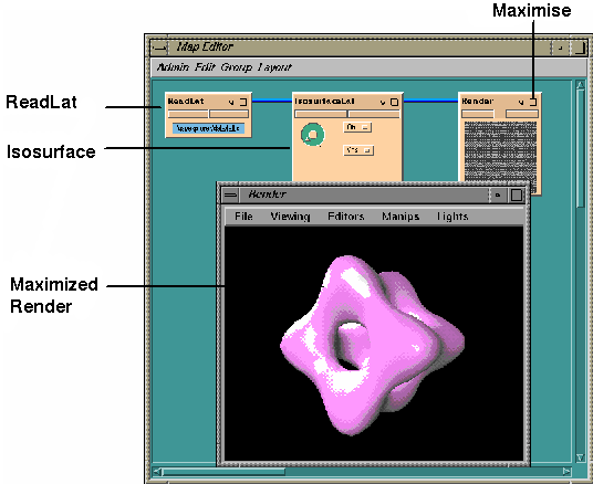
Figure 2-4 A Simple Map Example
For more information on using Render, see Chapter 3, Using Modules.
Modules
Modules are the individual units in a map. They are the mathematical
engines, powered by data, that make maps work. Although their
functions vary, they all share a basic structure (see Figure 2-5). Each module has a
visible form, its control panel, by means of which you can direct the
internal (and invisible) engine, or core.
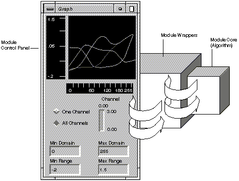
Figure 2-5 General Structure of a Module
What Modules Do
General Module Functions
Specific Module Functions
How Modules Work
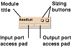
Figure 2-6 Micro Control Panel/Title Bar
Selecting a Module
Resizing the Control Panel
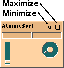
Figure 2-7 Diminutif Control Panel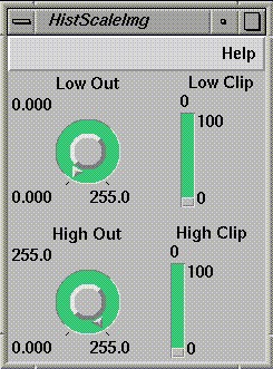
Figure 2-8 Full-scale Control Panel
Using the Pop-up Menu
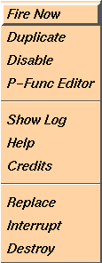
Figure 2-9 Module Pop-up Menu
Using Drag-and-Drop Operations
Getting Help
Each module has a Help window associated with it, which explains the
purpose of the module and lists its input ports, output ports, and
parameters.
Replacing Modules
Replace provides a convenient one step method of disconnecting,
destroying, re-invoking and reconnecting a module! This is
particularly useful when developing a module. The module can be
replaced, with the new version of the executable, in one easy
step. The new module is re-invoked with all the old's existing
connections, P-Func and Widget values. There are two ways you can
instigate a replace:
Wiring Module Ports Together
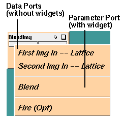
Figure 2-10 Module Input Ports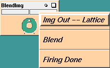
Figure 2-11 Module Output Ports
Making a Compatible Connection
Wiring Modules Together
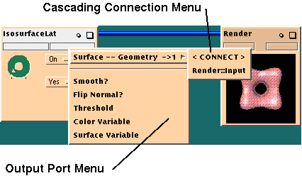
Figure 2-12 Making Connections between Modules
Connecting Several Modules
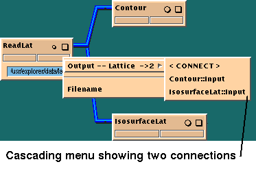
Figure 2-13 Making Multiple Connections
Disconnecting and Reconnecting Modules
Wire Routing
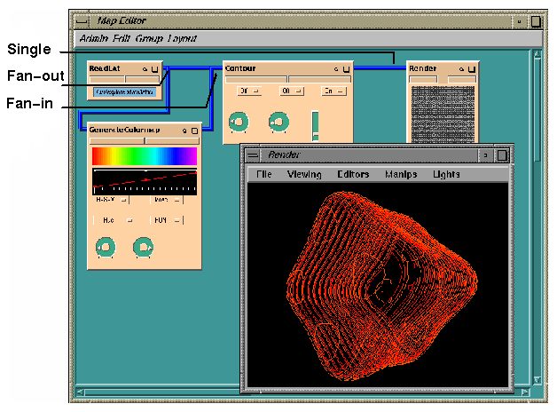
Figure 2-14 Example of Map Connections
Firing Modules
Forcing a Firing
Using the Synchronization Ports
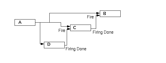
Figure 2-15 Controlling Module Firing with Fire Ports
Temporarily Disabling a Module
Each time you made a connection to the module or altered a parameter, you
would have to wait several minutes while it fired before you could continue.
You can avoid the wait by disabling the module while you complete your
operations, then enable it again when you are ready to fire the complete map.
If you disable a module that is connected in sequence with other modules, it
will not send new data to the modules that follow it. If those modules rely
entirely on the disabled module for data, they also cease to fire. The flow
of data will be blocked, along this branch at least, until you reenable the
disabled module.
Logging Module Output
Logging Map Data
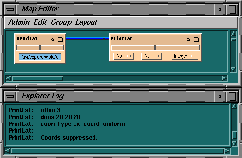
Figure 2-16 The Map Log Window
Logging Module Data
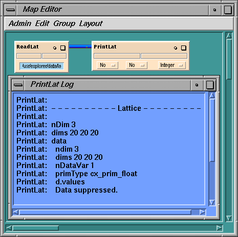
Figure 2-17 Module Log Window
Reviewing Log Messages
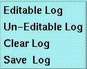
Figure 2-18 Log Window Pop-up Menu
explorer -debug printAlert
Understanding IRIS Explorer Data Types
Defining the Data Types
Using the Data Types
Looking at Module Data Types
Mixed Data types
Input Port Data
Modules
Lattice
Ball, BallStick, BoundBox, ChannelSelect, ColorXform, Contour, CropLat2D,
CropLat3D, DiffLat, DisplaceLat, GenerateColormap, Gradient, Graph,
Histogram, InterpLat, Interpolate, IsosurfaceLat, LatFunction, LatToGeom,
LatToPyr, Legend, MagnitudeLat, Mixer, MultiSlice, OrthoSlice, PrintLat,
ProbeLat, PyrToGeom, SampleCrop, ScaleLatNode, Shell, Slice, SubSample,
Transform, Triangulate2D, Triangulate3D, VectorGen, VolumeToGeom, WireFrame,
WriteLat
Pyramid
AtomicSurf, BallStick, BoundBoxPyr, CullPyr, CropPyr, IsosurfacePyr,
PrintPyr, PyrToGeom, PyrToLat, Transform, WritePyr
Geometry
Render, WriteGeom
Pick
Annotation, Ball, CropLat2D, CropLat3D, InterpLat
Output Port Data
Modules
Lattice
AtomicSurf, ChannelSelect, ColorXform, CropLat2D, CropLat3D, DisplaceLat,
DisplayImg, GenerateColormap, GenLat, Gradient, Histogram, Interpolate,
LatFunction, MagnitudeLat, Mixer, OrthoSlice, PyrToLat, ReadLat, ReadPlot3D,
Render, SampleCrop, ScaleLatNode, Shell, Slice, SubSample, Transform,
TransformGen, WaveFormColormap
Pyramid
CullPyr, CropPyr, LatToPyr, ProbeLat, ReadPyr, ReadPDB, Transform,
Triangulate2D, Triangulate3D
Geometry
Annotation, Ball, BallStick, BoundBox, BoundBoxPyr, Contour, CropLat2D,
CropLat3D, DrawText, IsosurfaceLat, IsosurfacePyr, LatToGeom, Legend,
MultiSlice, PyrToGeom, ReadGeom, VectorGen, VolumeToGeom, WireFrame
Pick
Render
Image Processing Modules
Table 2-3 lists some of the image processing
modules provided. Image processing modules manipulate lattices and
only accept and produce objects of the lattice datatype.
AbsImg
AddImg
AndImg
BlendAlphaImg
BlendImg
BlurImg
CompassAngleImg
CompassDirImg
CompassImg
ComplementImg
DisplayImg
DivImg
ExpImg
ForwardFFTImg
FourierConjgImg
FourierCrossCorrImg
FourierDivImg
FourierExpFltImg
FourierGaussFltImg
FourierMagnitudeImg
FourierMergeImg
FourierMultImg
FourierPhaseImg
FourierPwrImg
GaussBlurImg
GrayScaleImg
HistEqualImg
HistNormImg
HistScaleImg
InverseFFTImg
LaplaceEdgeImg
LogImg
MaxFltImg
MaxImg
MedianFltImg
MinFltImg
MinImg
MultImg
NegImg
OrImg
PowerImg
PseudocolorImg
RankFltImg
ReadImg
RobertsEdgeImg
RotZoomImg
SGIPaletteImg
SharpenImg
SobelEdgeImg
SqRootImg
SquareImg
SubtractImg
ThreshImg
WriteImg
XorImg
ZoomImg
Setting Module Parameters
Buttons
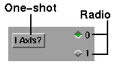
Figure 2-19 Button Widgets
Sliders
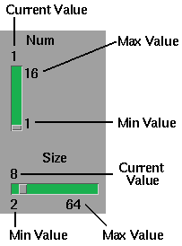
Figure 2-20 Slider Widgets
Dials
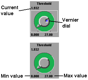
Figure 2-21 Dial Widgets
Text Type-in Slots
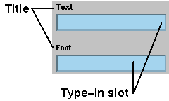
Figure 2-22 Text Type-in Slots
File Browsers
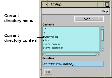
Figure 2-23 A File Browser
Option Menus and Scrolled Lists
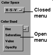
Figure 2-24 Option Menu Widgets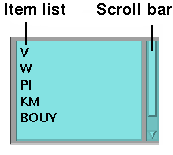
Figure 2-25 Scrolled List Widget
Drawing Areas
Figure 2-26 A Drawing Area Widget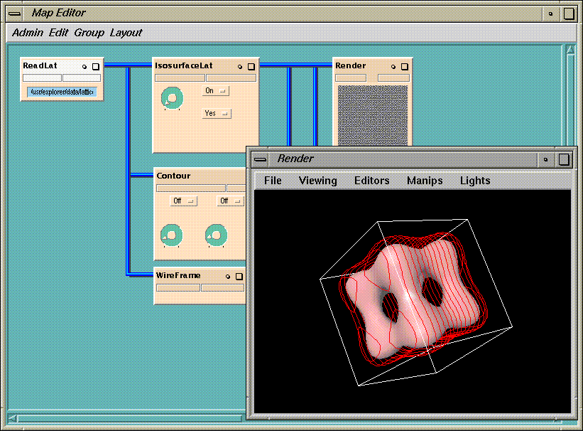
Figure 2-27 Experimenting with Widgets
Organizing the Module Librarian
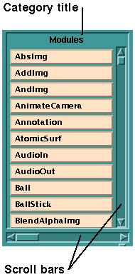
Figure 2-28 Module Category
Creating New Categories
Moving Modules Around
Storing Modules on the Shelf
Removing Modules from the Librarian
Saving the Librarian Configuration
category name module...
for each new category or
category shelf module..
for each module on the Librarian shelf.
Common Problems
You Need a Larger Memory Arena than Your System Can Give You
No Object Is Displayed in the Render Window
No Change in Object with Change in Parameters
Viewing Lattice Data in the Render Module
The Module Librarian Does Not Display a Saved Map
A Saved Map is Empty When Reopened
You need to save the map again. To prevent this from happening a
second time:
When You Try to Destroy a Module, Nothing Happens
When you select Destroy from the pop-up menu, IRIS Explorer
sends the module a message to exit. If the module is busy computing,
it may not get the message for a while. If you want it to quit
immediately, select Destroy again from the module pop-up
menu. This sends a kill message to the module's controller,
which then shuts down the module without waiting for a response from
the module itself.
You Cannot Launch a Module Librarian Remotely
If you get messages from the Local Controller (LC) or Global
Controller (GC) when you are trying to launch a Module Librarian for a
remote system, there is probably a command generating output from your
.cshrc file. You will see
the output from the command in the error message. For example, some
people print a message of the day from the .cshrc file.
You Get a Shared Library Error When You Launch Remote Module
Error messages that mention a shared library indicate that some part
of IRIS Explorer is not properly installed on the remote system. For
more information, see Remote Execution of Modules.
You Cannot Connect Two Modules, or a Module Produces Unexpected Data
You can check this in two ways:
Last modified: Mon Oct 13 12:30:02 1997
[ Documentation Home ]