IBM Visualization Data Explorer Programmer's Reference
[ Bottom of Page | Previous Page | Next
Page | Table of Contents | Partial Table of Contents | Index ]
Partial Table-of-Contents
This chapter describes the Data Explorer rendering model, introduces
additional elements of the data model relevant only to
rendering, and describes routines for manipulating
data structures for rendering.
(For descriptions of these routines, see
Appendix C. "Data Explorer Library
Routines".)
The Data Explorer renderer is designed for data visualization.
For example, it directly renders scenes described
by the Data Explorer data model (see Chapter 3.
"Understanding the Data Model").
The renderer handles all combinations of Groups and Fields as input
Objects.
The members of a Group or of a subclass of a Group (e.g., Series and
Composite Fields) are combined into one image by the renderer.
Rendering a scene involves fours steps:
- Transformation to world coordinates--Applying
transforms specified by transform nodes in the Object.
- Shading--Assigning colors to the vertices, using the intrinsic
surface colors, surface normals, surface properties specified by
Field components, and lights specified by Light Objects.
- Transformation to image coordinates--Applying
transforms specified by a camera Object.
- Tiling--Generating an image by interpolating point
colors and opacities across faces, and rendering volumes with a
rendering algorithm.
Transformation is the process of computing pixel coordinates from model
coordinates (i.e., the coordinates of the Object).
Because DXRender() performs necessary
transformations, most applications do not need
DXTransform() .
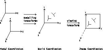
Transformation is essentially a two-step operation: (1) transform the
model coordinates of an Object into world coordinates; and (2)
transform the world coordinates into image coordinates
(see Figure 10).
Figure 10.
Transformation of Coordinates
The transformation from model to world coordinates is specified by
transform nodes (see 16.4 , "Xform Class")
in the description
of the input Object.
The transformation from world coordinates to image coordinates is
specified by a camera Object.
Object DXApplyTransform()
| Recursively applies a transform to an Object.
See DXApplyTransform.
|
[ Top of Page | Previous Page | Next
Page | Table of Contents | Partial Table of Contents | Index ]
[Data Explorer Documentation | QuickStart Guide | User's Guide | User's Reference | Programmer's Reference | Installation and Configuration
Guide ]
[Data Explorer Home
Page | Contact Data
Explorer | Same document on
Data Explorer Home Page ]
[IBM Home Page | Order | Search | Contact IBM | Legal ]

