Tiling is the process of combining shaded surface and volume
interpolation elements to produce an image.
The following table lists elements that are defined and implemented
("yes").
A dash identifies a meaningless combination.
| Component | irregular | regular | opaque | translucent |
|---|---|---|---|---|
| "lines" | yes | yes | yes | yes |
| "triangles" | yes | -- | yes | yes |
| "quads" | yes | yes | yes | yes |
| "tetrahedra" | yes | -- | -- | yes |
| "cubes" | yes | yes | -- | yes |
| "faces," "loops," "edges" | yes | -- | yes | yes |
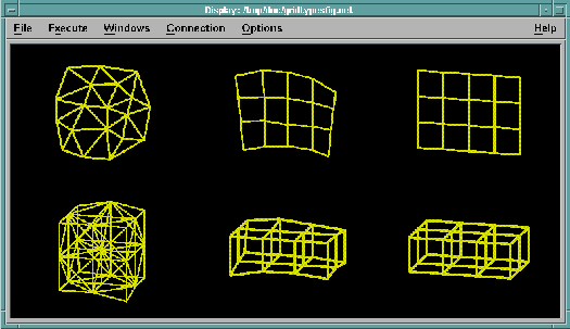
Lines may be irregular unconnected vectors or paths having regular 1-dimensional connections. Surfaces and volumes may be (1) completely irregular, (2) regular in connections but irregular in positions, or (3) regular in both connections and positions (Figure 11).
Figure 11. Types of
Connections and Positions

The interpretation of "colors" and "opacities" differs between surfaces and volumes. For surfaces, a surface of color cf and opacity o are combined with the color cb of the objects behind it, resulting in a combined color cfo + cb (1 - o).
For volumes, the "dense emitter" model is used, in which the opacity represents the instantaneous rate of absorption of light passing through the volume per unit thickness, and the color represents the instantaneous rate of light emission per unit thickness. If c(z) represents the color of the object at z and o(z) represents its opacity at z, the total color c of a ray passing through the volume is given by: c % = % integral to infinity from < - infinity > % c ( z ) % 'exp' % left lparen minus integral to < z > from < - infinity > % o ( zeta ) d zeta right rparen % dz
Tiling options are controlled by a set of Object
attributes.
These attributes may be associated with Objects at any level of a
Field/Group hierarchy.
The attributes may be set by using the
DXSetAttribute()
function, or by using the Options
module.
The attributes are:
| Attribute | Meaning |
|---|---|
| "fuzz" | object fuzz |
Object fuzz is a method of resolving conflicts between objects at the same distance from the camera. For example, it may be desirable to define a set of lines coincident with a plane. Normally it will be unclear which object is to be displayed in front. In addition, single-pixel lines are inherently inaccurate (i.e. they deviate from the actual geometric line) by as much as one-half pixel; when displayed against a sloping surface, this x or y inaccuracy is equivalent to a z inaccuracy related to the slope of the surface. The "fuzz" attribute specifies a z value that will be added to the object before it is compared with other objects in the scene, thus resolving this problem. The fuzz value is specified in pixels. For example, a fuzz value of one pixel can compensate for the described half-pixel inaccuracy when the line is displayed against a surface with a slope of two.
[Data Explorer Home Page | Contact Data Explorer | Same document on Data Explorer Home Page ]