In general, macros are higher level processing functions that are constructed from simpler ones. A Data Explorer macro is a sequence of modules collected together that you can use as a single tool. This is useful if you have a sequence of modules that provide a function that you need frequently in your visual programs. Macros can help make your visual programs simpler by combining several tool icons into one.
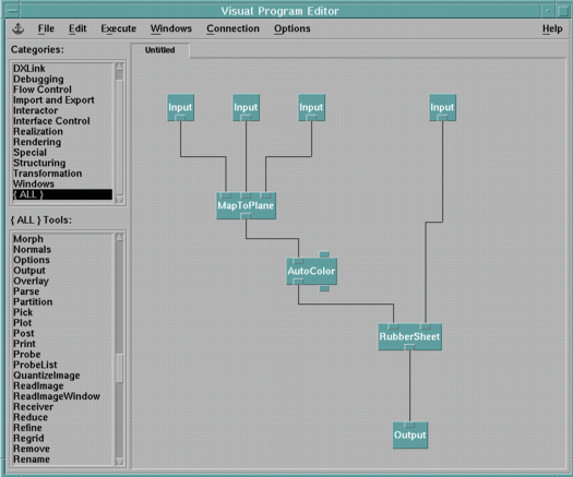
Macros are themselves visual programs and are created in much the same way. For example, the macro represented in Figure 75 maps data onto a plane, colors it, and then performs a deformation using the RubberSheet module. It is constructed by placing the appropriate tool icons on the VPE canvas and connecting them.
Note: You can also create a macro directly from a visual program in the VPE window.

Macro's inputs and outputs are represented by the Input and Output tools from the Special category. A macro has at least one input or output.
| Note: | Macros cannot include interactors, Sequencers, colormaps, probes, picks, Display, or Image tools. |
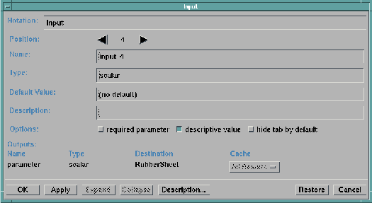
Place the Input icon on the canvas and connect it to the appropriate tool icon input tab. The Input type conforms to that of the input tab to which it is connected. Like other tools, the Input icon can be connected to multiple input tabs. You can use the Configuration dialog box for the Input tool (Figure 76) to specify:
Some of these values are, by default, inherited from the input tab to which the Input tool is connected, but many of them can be changed from the Configuration dialog box.
Figure 76. Input
Configuration Dialog Box

Position | Specifies the tab position this input occupies on the resulting macro icon. By default, the tab positions are assigned in the order that you select the Input icons from the tool palette. For example, the first icon you drag over to the canvas has position 1, the second has position 2, and so on. If an input is deleted from a macro, the position of the other inputs are not automatically changed. For example, if the input at position 2 of a macro with three inputs is deleted, the other two inputs remain at positions 1 and 3, with position 2 left empty. Each input must have a different value for position. |
Name | Specifies the name of the input. This field must begin with a letter, and no spaces or special characters, except for the at-symbol (@) and the underscore character (_), are allowed. |
Type | Specifies the type of the input. The type conforms to the inputs that the Input tool is connected to. When connecting it to more than one input, the Input tool assumes the type of the most restrictive input to which it is connected. For example, if the Input tool is connected to two inputs, an object and a scalar, the Input tool type would become a scalar type. |
Default Value | Specifies a default value for the input. If the descriptive value toggle button is activated, the default value field of the macro is treated as a description, not an actual value. You can use this to indicate to users of the macro what sort of parameter this input should be. |
Description | Provides a short description of the input for your own documentation purposes. This description is used to generate the Description window for the resulting macro tool, which you can access through its Configuration dialog box. |
Options | The required parameter toggle button, when activated, indicates that the input is required for the macro. The corresponding input tab of resulting macro icon is highlighted with a different color. This option is inherited from the input to which the Input tool is connected. The descriptive value toggle button is used with the Default Value field, as described above. |
Specify the macro's outputs with the Output tool from the Special category. Place the Output tool icon on the canvas and connect it to the appropriate output tab from another tool icon. The Output also inherits its type from the output tab to which it is connected.
The Configuration dialog box for the Output tool is similar to the one for Input, but the Options toggle buttons and the Default Value field are grayed-out.
Before you can use the macro, you must first name it, save it, and then load it, making it available in the tool palette.
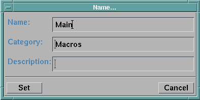
To name the macro, select the Macro Name option from the Edit pull-down menu. The Name... dialog box opens. The Name dialog box for the example macro is illustrated in Figure 77. Type a name for the macro in the Name field. The name must consist only of letters and numbers (no spaces or underscores), and must begin with a letter. By default, the macro is assigned to the "Macros" category. You can assign the macro to a different category by typing a new name in the Category field. The category you choose can be a new or existing category.
Figure 77. Macro
Name Dialog Box

To save the macro after it has been named, use the Save As... option of the File pull-down menu. Because macro files are saved as visual programs, and therefore have .net extensions, it may be helpful to organize them in a separate directory to distinguish them from other visual programs.
| Creating Macros the Easy Way |
|---|
|
(Ref #7.)
For use in other visual programs or to simplify the "network" that appears in the VPE canvas, you may want to combine some of the tools of a visual program in a single macro. This can be done directly and easily in the VPE window if the selection includes only allowed tools (see preceding Note, page reference #6).
|
For a macro to be available for use, it must be loaded into the tool palette. To load a saved macro:
| Note: | If the macro you loaded has the same name as a macro previously loaded, the "new" macro replaces the earlier one, whether or not they were assigned to the same category. |
When the new macro is available for use, it is listed in the tool palette as a member of the category you assigned it to. For example, the MapAndDeform macro would be listed under the MyMacros category.
When you save a visual program which uses a macro, the path to the macro is saved in the visual program. When you reload the visual program, the macro will automatically be loaded for you from the same location, so it will only be necessary to explicitly load the macro if it has been moved to a new location. You can also easily see what macros need to be included with a visual program, if for example, you are sending a visualization program to another user. Simply look at the top of the .net file for the list of referenced macros.
You can configure Data Explorer to automatically load macros from a specified directory when you begin the Data Explorer program. To do this, use the -macros pathlist option when starting Data Explorer, where pathlist specifies one or more paths where the macros can be found. Alternatively, you can use the DXMACROS environment variable. For more information on how to do this, see "Using Environment Variables", and C.1 , "Environment Variables".
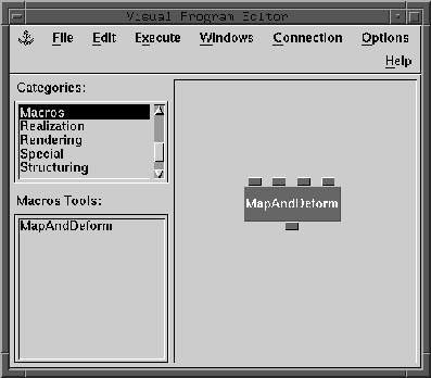
After you have created and loaded a macro, you can use it the same way you use other Data Explorer tools. Simply select it from the tool palette and place the icon on the canvas. Figure 78 shows the new icon created for the MapAndDeform macro.
Figure 78.
MapAndDeform Macro Icon

The macro has a Configuration dialog box describing the input and output parameters. You can open the dialog box by double-clicking on the macro icon.
After you place a macro in a visual program, it is possible to view the macro contents and to change some of the tools inside the macro.
To open a macro:
You can repeat these steps for any macros contained in the newly opened VPE, until only modules are present in the window.
With the macro opened, you can change the tools inside the macro. However, you cannot change the number or ordering of inputs or of outputs.
Changing the tool in a macro affects only the current visualization session. If you want the changes to be permanent, you must save the changed macro, using the Save or Save As... options. If you want to restore the definition of the macro to the way it was before you modified it, close the VPE window containing the macro (without saving) and reload the macro from the main VPE window.
[Data Explorer Home Page | Contact Data Explorer | Same document on Data Explorer Home Page ]