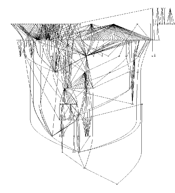
Figure 1 shows a call graph derived from files in the src
directory from Mosaic 2.7b. The files examined were restricted to those
matching the pattern *gui*. Each node in the call graph
represents a procedure defined in one of the selected files, or a procedure
called by a procedure defined in the selected files. The node at the source of
a directed edge represents the calling procedure; the node at the tail of the
directed edge represents the called procedure.

Figure 1
Figure 2 also shows a call graph for all files with "gui" in their name, but in this case the nodes are restricted to those defined within the selected files.

Figure 2
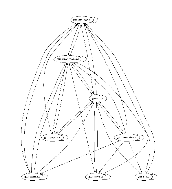
The call graph in Figure 3 is derived from the same data used to derive the call graph in Figure 2, but the nodes in the call graph in Figure 3 represent files. The file represented by a node at the source of a directed edge contains a procedure that calls a procedure contained in the file represented by the node at the destination of the directed edge.

Figure 3
This page last modified on 23 September 1997.