Stage 1
Design, Manufacture, and Setup
Mechanical Design
Motors
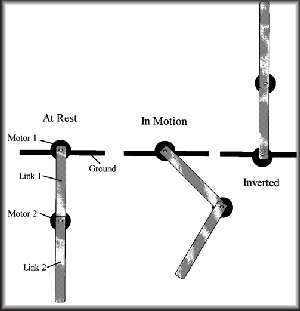
In the design of the acrobot, we wanted to get very low friction.
In order to achieve this, the motor at the hip joint is direct drive (this
means there is no gearbox between the motor and the device it actuates).
For the hand joint, we only needed bearings and an encoder, but we chose
to simply get a motor identical to the hip joint motor and not power it,
for the sake of simplicity. The motors we selected are Maxon
Rare Earth Magnet motors with factory installed HP encoders (Order # RE025-055-37EBA201A
(motor) and HP-HEDS-5540-A02 3409.030-050 (encoder) )
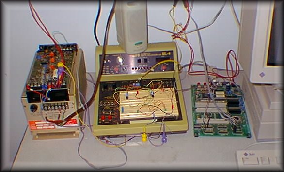
Amplifier (above left)
The amplifier that we used is a EG+G Torque Systems Model CO 501-002D.
This is a current controlled amplifier, which means that the current output
of the amplifier is directly proportional to the voltage input, with this
model having an input/output ratio of 2.4 amp/volt.
Diagram of connections
Interface circuit (above middle)
The purpose of the interface circuit is to get the correct voltage
out of the 332 signals to send to the amplifier. The 332 would issue
a 5V signal to one line if it wanted positive torque, and would issue a
5V signal to another line if it wanted a negative torque. The interface
circuit uses relays and potentiometers (adjustable resistors) to supply
the amplifier with the appropriate voltage for the desired motor current.
Circuit picture
Circuit diagram
Motorola 68332 (above right - also referred to as
a 332)
Sun Workstation